There are no products listed under this category.
Easy Jig Gen 3
Multi-platform AR-15, AR-9, and AR-10/LR308 jig setup, drilling, milling, finishing, and router compatibility notes.
There are no products listed under this category.
Download PDFs, view install notes, and find answers to common customer questions in one clean support hub.
Grab the PDF first for the cleanest diagrams, then expand the how-to sections below for quick reference.
Multi-platform AR-15, AR-9, and AR-10/LR308 jig setup, drilling, milling, finishing, and router compatibility notes.
Multi-platform AR-15, AR-9, AR-45, AR-10, and LR308 jig assembly, milling, drilling, and finishing instructions.
Operator’s manual for the 80% Arms high-speed precision milling router used with 80% Arms SpeedMill tools.
Ambidextrous bolt catch and extended paddle installation instructions.
Setup notes for the billet aluminum modular grip for the SIG Sauer P365 platform.
Installation instructions for the ambidextrous safety selector, levers, detent, spring, and throw adjustment.
Need the short version? Expand the instructions below without leaving the page.
This quick reference covers the Easy Jig Gen 3 multi-platform setup for AR-15, AR-9, and AR-10/LR308 lowers, including router adapter installation, jig assembly, pilot drilling, milling templates, final drilling, finishing, and troubleshooting notes.
Unplug the router, remove the factory router plate and adjustable base, remove the collet, and confirm the spindle and SpeedMill are clean and free of debris.
Install the correct SpeedMill size for your router, then install the router adapter plate using the correct mounting method for your router model.
Align the buffer screw support with the lower receiver and loosely thread the buffer screw through the support into the lower.
Install the correct front takedown pin block to the top plate, then loosely attach the side walls to the top plate.
Use a 3/8” drill bit through the side wall bushings to align the walls, then tighten the side walls to the top plate.
Place the lower receiver into the jig, align the front takedown pivot pin holes, and insert the correct takedown pin for the platform.
Tighten the buffer screw and fasten the buffer screw support to the top plate. Periodically check these screws during milling.
Attach the drill block, mount the jig correctly in the vise, and drill the pilot hole with the 21/64” drill bit using cutting fluid.
Mill Template 1 with the short guide pins, using slow clockwise motion and advancing one hash mark per pass.
Mill Template 2 with the medium guide pins, then stop before moving to the next depth gauge.
Mill Template 3 with the long guide pins until the trigger slot is completely formed.
Drill trigger, hammer, and selector holes using the 3/8” and 5/32” bits. Drill through one wall at a time, then reposition the jig and repeat for the other wall.
Remove the lower from the jig, deburr drilled holes, clean the receiver, and inspect the safety selector detent hole for chips or burrs.
This quick reference covers the GEN-4 Easy Jig multi-platform system for AR-15, AR-9, AR-45, AR-10, and LR308 lowers, including jig assembly, pilot hole drilling, router adapter plate setup, FCG milling, fire selector and pin hole drilling, router tips, and final finishing.
Align the Buffer Support Plate [D] with the back of the lower receiver, making sure the indexing protrusion and ribs face the lower receiver.
Loosely finger-thread the Buffer Screw [E] through the buffer support plate and into the lower receiver.
Attach the Pivot Adapter [C] to the Top Plate [A] using 2 Jig Screws [G].
Orient both Side Walls [B] with the larger 3/8” bushings toward the rear, then set the top plate on the side walls with the numeral “3” visible through the top plate.
Loosely attach both side walls to the top plate using 6 jig screws. Use 3/8” and 5/32” drill bits through the side wall bushings to align the walls, then tighten the screws and remove the bits.
Insert the receiver assembly upward from the bottom of the side walls toward the top plate.
Align the lower receiver’s pivot pin holes with the pivot adapter and insert the correct quick pin. For AR-15, AR-9, and AR-45, use the smaller rearward pivot adapter hole and silver AR15 Quick Release Pin [H]. For AR-10/LR308, use the larger forward pivot adapter hole and black 308 Quick Release Pin [I].
Fasten the buffer support plate to the rear of the top plate using 2 jig screws. Use the inner mounting points for AR-15/9/45 and the outer mounting points for AR-10/LR308.
Tighten the buffer screw using a small screwdriver or hex wrench, then attach the Drill Guide [F] to the top plate using 2 jig screws.
Secure the completed jig assembly in a vise by the notches at the bottom of the side walls. Do not clamp the jig by the faces of the side walls.
Drill the pilot hole with the 21/64” drill bit using cutting fluid. Keep the drill straight and perpendicular, clear chips often, and continue until the bit exits the bottom of the receiver.
Install the router adapter plate and correct SpeedMill for your router. Confirm the router base lock/latch is tight and functioning before milling.
Mill FCG Step 1 with the short guide pins and Depth Gauge #1. Use small clockwise overlapping motions, clear material each pass, and trace the perimeter until material is no longer being removed.
Switch to the medium guide pins and mill FCG Step 2 with Depth Gauge #2, advancing one hash mark or less per pass and applying cutting fluid before each pass.
Switch to the long guide pins and mill the trigger slot with Depth Gauge #3 until the trigger slot is completely formed.
Clamp the jig on its side and drill the fire selector and pin holes. Drill through only one side of the receiver wall, then flip the jig and repeat for the other side.
Remove the receiver from the jig, clean out chips and cutting fluid, inspect drilled holes for burrs, and pay close attention to the safety selector detent hole.
This quick reference covers the FST-1 high-speed precision milling router, including basic safety, assembly, SpeedMill installation, subbase removal, base locking lever adjustment, operation, depth of cut, and maintenance reminders.
Read the operator’s manual before using the router. Always wear eye and hearing protection when using power tools.
Inspect the router and accessories before use. Do not use the tool if it is missing parts, damaged, or not fully assembled.
Unplug the router before assembly, adjustments, changing accessories, removing the base, or performing maintenance.
To remove the base, open the quick release lever, hold the base with one hand, hold the top of the router with the other, and pull the motor housing away from the base.
To install the SpeedMill, remove the base, depress the spindle lock, loosen and remove the collet nut and collet, then thread the #3C 80% Arms SpeedMill onto the spindle and tighten with a wrench.
Do not remove the protective end mill tip cover until ready to begin milling.
Remove the subbase before using the router with an Easy Jig Gen 2 or Gen 3 router adapter plate.
Check the quick release locking lever before use. The base should not slip when pressure is applied. Adjust the tension hex nut only as needed.
Before starting the router, confirm the SpeedMill is securely tightened, the depth of cut is set to the correct Easy Jig hash mark, and the end mill flutes are not touching the workpiece.
Turn the router on with the front switch and wait until it reaches full speed before contacting the workpiece.
Hold the router firmly with both hands during operation, avoid forcing the feed rate, and allow the cutter to take small, clean cuts.
After each pass, turn the router off and wait for the cutter to come to a complete stop before lifting the router from the work surface.
Use the Easy Jig depth gauge when setting depth of cut. Do not exceed one hash mark per pass. For best finish quality, use half-hash-mark passes or less.
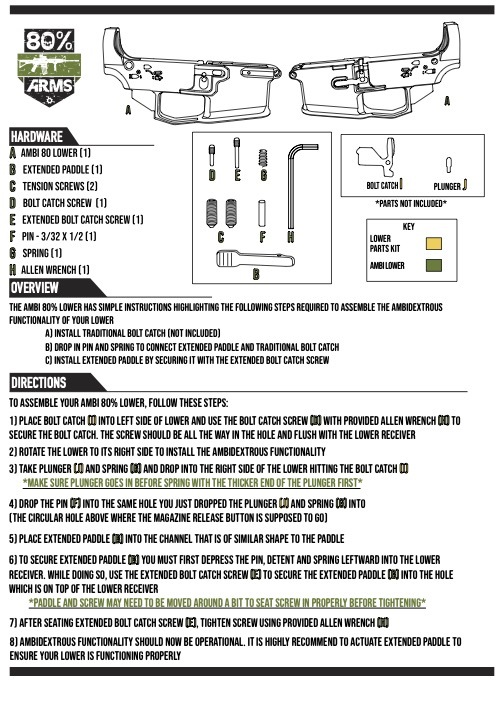
These steps walk through installing the traditional bolt catch, connecting the ambidextrous components, securing the extended paddle, and checking that the right-side control functions properly.
Place the Bolt Catch [I] into the left side of the lower. Use the Bolt Catch Screw [D] and provided Allen Wrench [H] to secure it. The screw should sit fully inside the hole and flush with the lower receiver.
Rotate the lower to the right side to install the ambidextrous functionality.
Drop the Plunger [J] and Spring [G] into the right side of the lower so they contact the Bolt Catch [I].
Drop the Pin [F] into the same hole used for the plunger and spring. This is the circular hole above where the magazine release button installs.
Place the Extended Paddle [B] into the matching paddle-shaped channel.
Depress the pin, detent, and spring leftward into the lower receiver. While holding them in place, use the Extended Bolt Catch Screw [E] to secure the extended paddle through the hole on top of the lower receiver.
After seating the Extended Bolt Catch Screw [E], tighten it with the provided Allen Wrench [H].
Actuate the extended paddle to confirm the ambidextrous functionality is operating properly.
For the clearest version, use the downloadable PDF above.
This manual covers the grip base, dust cover options, grip panel options, optional O-rings, grip extension components, and FCU installation notes for the S365 modular grip.
Set the optional FCU O-Ring [F] in place.
Drop in the FCU. The FCU is not included with the grip.
Fix the FCU in place by installing the spear pin from left to right as shown in the original manual.
Slide the desired Dust Cover [B] on from the front until it aligns with the screw hole in the Grip Base [A].
Fasten the dust cover with the Dust Cover Screw [D].
These steps cover installing the ambidextrous safety selector cylinder, long and short selector levers, detent, spring, grip, and final function check.
Insert the Safety Selector Cylinder [A] into the selector hole on the lower receiver, with the smooth end on the driver side and the grooved detent channel end on the passenger side.
Place the Long Selector Lever [B] onto the safety selector cylinder on the side of your dominant-hand thumb.
Align the tabs on the bottom of the lever with the slot on the end of the cylinder, then fasten them together using a Screw [D] and the provided Torx Wrench [E].
Turn the selector lever to SAFE and make sure it stays in position.
Drop the selector detent, pointed end first, into the selector detent hole above the grip fin on the passenger side of the lower receiver. It should sit completely below flush.
Place the selector spring into the hole on the top side of your grip.
Slide the grip with spring onto the lower receiver’s grip fin until it is completely flush, making sure the spring does not kink or bind as it enters the selector detent hole.
Maintain upward pressure on the grip and finish attaching it to the lower receiver by fastening the grip screw through the open bottom end of the grip.
Install the Short Selector Lever [C] on the remaining end, repeating the alignment and fastening steps. Make sure both levers point simultaneously toward either SAFE or FIRE.
With the assembly unloaded and cleared, function test the selector by switching from SAFE to FIRE and back a few times.
Need help with an order, shipping update, product compatibility, return, warranty claim, or showroom visit? Start here.
Once your order has been processed and shipped, you will receive an automated email containing your tracking number. If you have not received an update, please check your spam or promotions folder.
During high-volume periods, sales, or regulatory changes, processing times may be longer than normal.
Manual Verification Required is a standard payment security review. In some cases, our team may need to verify the payment method used before the order can continue processing.
No action is required unless our support team contacts you directly.
Lead times can vary depending on order volume, product availability, and current demand. Orders containing high-demand items, including jigs, may take longer to process.
Our team is working to process all orders as quickly as possible, and tracking will be sent automatically once your order ships.
Address changes can only be made if the order has not entered the fulfillment process. If you need to update your address, contact support immediately with your order number.
Once a tracking number has been generated, we are unable to reroute the package.
The GST-9 MOD100 frame is designed for modularity and is compatible with Gen 3 Glock-style components. Depending on the configuration, it can be used with Glock 19 or Glock 17 length slides with the appropriate extensions.
The Easy Jig Gen 3 is a multi-platform jig designed for AR-15, AR-9, and .308 lowers. Router compatibility can vary, so always check your router and tool kit specifications before beginning.
Digital PDF manuals and installation instructions are available above on this page. If you cannot find the correct manual or your physical instructions are missing, contact support and we can help provide the latest version.
Many 80% products and jigs can ship directly to your home where legally permitted. Completed frames, serialized items, or certain restricted-state orders may require an FFL transfer.
If an FFL is required for your order, our team will contact you with the next steps.
Returned items must be shipped using a service with tracking and must include a printed copy of your email correspondence or original invoice.
Items must be returned in the same condition and original packaging as they were shipped, with no signs of use.
Any item that has been milled, drilled, modified, damaged, or used is not eligible for return.
Once your return is received and inspected, a refund will be issued to your original payment method, minus any applicable shipping costs or processing fees.
Please allow several business days for the refund to appear on your bank statement.
If you need to cancel your order, please contact support as soon as possible with “Request To Cancel” and your order number.
Orders can only be canceled if they have not been sent to the shipping floor or entered fulfillment.
Please inspect your shipment immediately after delivery. If an item is missing, contact us within 7 days with your order number and photos of the items and packaging received.
Our team will review the shipment details and work toward a resolution.
If you believe a product is defective or out of spec, please send clear photos or videos of the issue along with your order number.
Our technical support team will review the claim and assist with the next steps if a manufacturing defect is confirmed.
Yes. Visit the 80% Arms showroom at 309 Palette Drive, Fort Worth, TX 76140. Showroom hours are Monday through Friday, 9 AM to 3 PM.
Email support@80percentarms.com or call 949-354-2767. Phone and live chat hours are Monday through Friday, 8 AM to 4 PM CST.
Contact support if you need help with an order, compatibility question, missing item, warranty claim, or anything that does not match the instructions above.
Shipping restrictions can vary by state, city, county, product type, and current law. This reference is provided as a general overview only. Customers are responsible for understanding their local laws before placing an order.
The table below summarizes state and local restriction references, including the law, bill, ordinance, or public act listed for each area.
| State / Area | Law / Ordinance Reference | General Restriction Notes |
|---|---|---|
| California | AB 1621 | Restrictions on firearm precursor parts, unfinished frames/receivers, jigs, tooling, and certain related items. |
| Colorado | Senate Bill 23-279 | Restrictions on unserialized firearms and unfinished frames or receivers. |
| Connecticut | Public Act No. 19-6 / Substitute House Bill No. 7219 | Restrictions on untraceable firearms, unfinished frames/receivers, and certain unserialized items. |
| Delaware | 2021 ghost gun legislation | Restrictions on unserialized firearms, unfinished frames/receivers, and related distribution. |
| Hawaii | HB 2744 | Restrictions on firearms and firearm components without serial numbers. |
| Illinois | Public Act 102-0889 | Restrictions on unserialized firearms and unfinished frames/receivers. |
| Maine | LD 1126 | Restrictions related to homemade or untraceable firearms requiring serialization. |
| Maryland | HB 425 | Restrictions on unserialized firearms and unfinished frames/receivers. |
| Massachusetts | S.2572 / HD.4420 | Restrictions on unserialized firearms, frames, receivers, jigs, tooling, and related items. |
| Nebraska / Omaha | Omaha ghost gun ordinance | Omaha has local restrictions on unserialized firearm frames and receivers. |
| Nevada | 2021 unfinished frame/receiver law | Restrictions on unfinished frames/receivers and unserialized firearms. |
| New Jersey | 2018 ghost gun legislation | Restrictions on ghost guns, firearm build parts, and related manufacturing/distribution activity. |
| New York | Senate Bill S14A / Jose Webster Untraceable Firearms Act | Restrictions on unfinished frames/receivers and untraceable firearms. |
| Oregon | HB 2005 | Restrictions on unserialized firearms and unfinished frames/receivers. |
| Pennsylvania Local Areas | Philadelphia, Delaware County, Reading, York, Harrisburg, Erie, and other local ordinances | Some cities and counties have local restrictions on ghost guns, unfinished receivers, and related items. |
| Rhode Island | 2020 ghost gun law | Restrictions on untraceable firearms, undetectable firearms, and unserialized firearms. |
| Vermont | S.209 / Vermont Ghost Guns Act | Restrictions on unserialized firearms, frames, and receivers. |
| Washington | HB 1705 and HB 1240 | Restrictions on unfinished frames/receivers and certain firearm parts/products classified under state law. |
| Washington, D.C. | D.C. Law 23-125 / D.C. Code § 7-2505.01 | Restrictions on ghost guns, unfinished receivers, and unserialized firearm parts. |
California orders may be subject to additional restrictions, verification requirements, or FFL requirements depending on the product ordered.
Please complete any requested verification promptly to avoid delays or cancellation.
We monitor state and local regulations closely. If your order contains a product that is restricted in your state, the order may be canceled and refunded.
Customers are responsible for understanding their local laws before placing an order.
Our customer support team is here to help with order questions, technical support, warranty claims, product compatibility, and showroom questions.